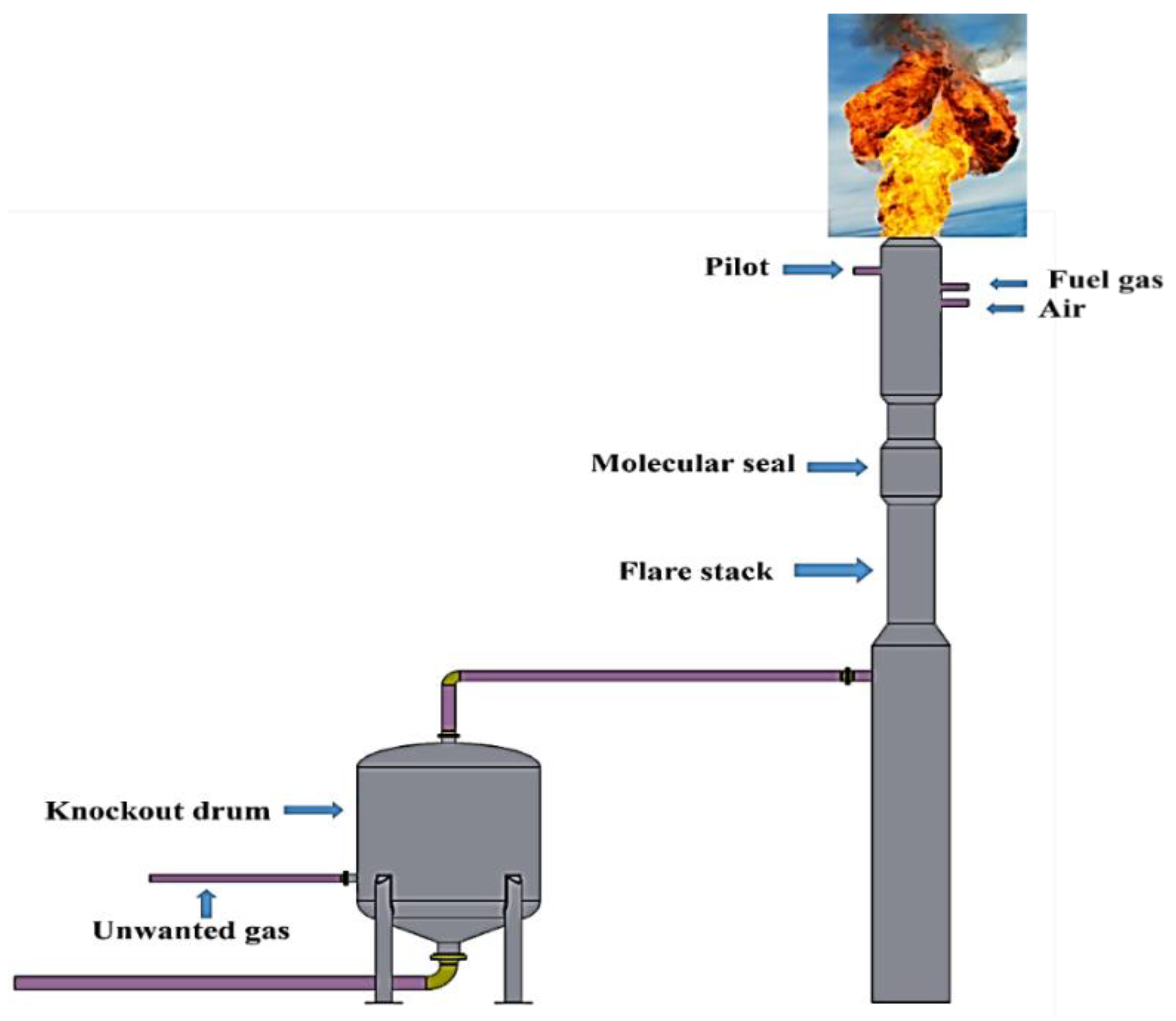
The design of the flare tip is more often than not just an open pipe that cant really aide gasair mixing and exhibit low radiation unless water steam air gas is used as an assist media. Flare Tip Molecular Seal Also known as flare stacks flare tips molecular seals are elevated vertical conveyances found in oil gas wells rigs refineries chemical natural gas plants and landfills.
2
The sealing-fluid depth in most staging seal drums is typically in the range of 2 to 5 psig which is equivalent to 5 to 125 ft of water column.
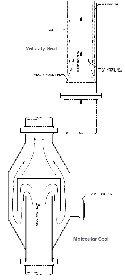
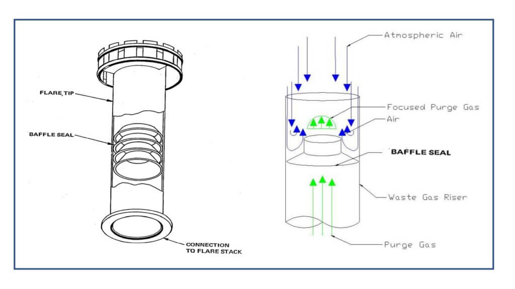
. The seal is a gas inversion device causing the gas normally flowing in an upward direction to be turned. AFS MOLECULAR SEALS The Molecular Seal AFS Series is located just below the flare tip and has been designed to prevent air ingress to the flare riser thus preventing the formation of an explosive mixture in the system. The flare vendor will have to provide details on design options and required purge flow.
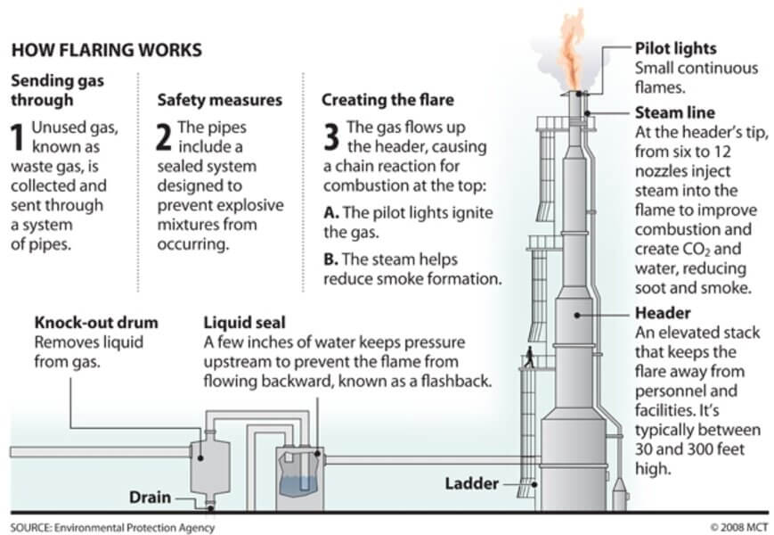
They are used to eliminate waste gas that cannot be otherwise used or transported. Controls are required for the ignition and monitoring of flare system pilots control of fluid levels in knockout and liquid seal drums for the control of steam or air or water or gas injection for control of smoke measurement of oxygen measurement of lower heating value adjustment of assist gas. Flare systems require many different types of controls.
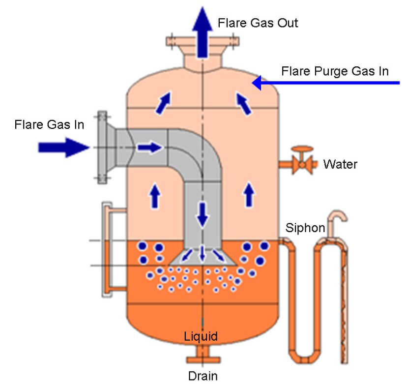
On the other hand a water seal drum uses the same way except that the sealing fluid is water and the drum is instaled at the flare stack base after the knock-out drum vessel whereas moleculare seal is instaled at the top of flare stack before the tip. Tan View Determination of the Minimum Safe Purge Gas Flow Rate in Flare Systems with a Velocity Seal Article Jan 2014. The flare system.
The emissivity factor or F-factor ranges between 020 and 035 for these flares although lower values for hydrogen can be used. ABSTRACT OF THE DISCLOSURE An improved molecular seal for installation in a flare stack system designed for burning of waste gases of lesser density than air and for installation at an intermediate point in the flare stack. The molecular seal included a drain line with a U-seal and isolation valve at the bottom.
The flare vendor will have to provide details on design options and required. Molecular seal creates a labyrinth to more. A molecular seal also could be very efficient in reducing the amount of purge gas required to maintain a positive pressure in.
The large quantity of gas vented after the com-pressor tripped blew the oil in the molecular seal out of the flare. The seal has a housing of larger cross-section than that of the flare stack the housing being closed by plates at both ends with an outlet conduit sealed. As indicated in figure-1 liquid seal at the flare stack base is essentially a.
Flare System Design Simplified Article Jan 1967 HYDROCARB PROCESS SH. The molecular type seal forces the purge gas to make two U turns forming a seal because of the different molecular weights. An improved molecular seal for installation in a flare stack system designed for burning of waste gases of lesser density than air and for installation at an intermediate point in the flare stack comprising a housing of larger cross-section than that of the flare stack the housing being closed by plates at both ends with an outlet conduit sealed through the plate at the outlet end of the.
Different velocity seal model viz. In a deep seal drum the depth of the sealing fluid is designed to be equal to the staging pressure of the staged flare system. Flare System Design for Oil and Gas Installations Flare Seal Drum Primary Duty To prevent flashback from flare tip back to flare headers To avoid air ingress into flare system during.
The molecular seal is located just below the flare tip and is designed to prevent the ingress of air into the flare stack at low flow rates The molecular seal minimises the amount of continuous purge gas usage Gas normally flowing in an upward direction is turned through 180 degree to the direction of flow. 2-9 27 Data Removed After Being Considered. 40 5 0 60 and 70 were created and it is found that when the baffle to tip area reduction was 50 there was an.
Although the flare designer provided a drain for the molecular seal the PHA team did not recognize that oil could be carried over when the amount of leaking gas increased and operators never opened the valve in the drain line. However fluidic seals require more purge gas than molecular seals. Purge flow is required to prevent air ingress into the flare stack.
DuhonGATE Chemical 27 Jun 08 1751. Molecular seal recommended for flare tips 24 and larger DESIGN FEATURES Molecular seal can maintain an effective seal for up to 8 hours after loss of purge gas supply Velocity seal. One is a gas seal called a molecular seal.
Molecular seal is an unfortunate name given to a flow restriction installed in a flare stack to minimize the amount of purge gas required. MortenA Petroleum 29 Jun 08 1608. The molecular seal included a drain line.
Flare System Part Flare Process Flare Drums Flare Seals The Piping Talk
Purge Reduction Seals Velocity And Molecular Seals Encore Combustion

Buoyancy Seal And Velocity Seal For Flare Stack Enggcyclopedia
Flare System Part Flare Process Flare Drums Flare Seals The Piping Talk
Materials Free Full Text Failure Analysis Of A Flare Tip Used In Offshore Production Platform In Qatar Html

Buoyancy Seal And Velocity Seal For Flare Stack Enggcyclopedia

Pdf Purge Reduction Device A Guide To The Selection Of Gas Seal In A Flare System
Flare System Part Flare Process Flare Drums Flare Seals The Piping Talk
0 comments
Post a Comment